Flash Parapit Wall To High Roof Wall

Image Result For Concrete Parapet Wall Detail Parapet Roof Garden Roof

Moisture Management Of Parapet Walls Masonry Technology Inc

Steel Stud Parapet Old Timer Wood Blocking And A Cant Anchored To The Structural Deck Restrain Architecture Details Roof Construction Architecture Building

Typical Parapet Wall Detail Parapet Architecture Details Flat Roof

David Suzuki Parapet Detail Xl Jpg 1000 750 Parapet Architecture Details Architecture

Pin On Construction Details

Architects of ultra modern.
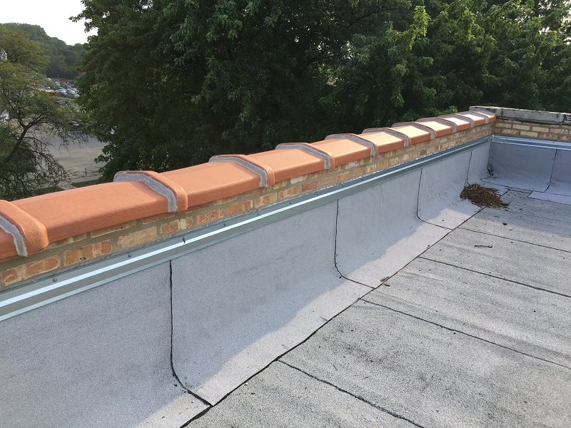
Flash parapit wall to high roof wall.

Tamlyn

Cmu Parapet Wall Roof Detail Wood Architecture Detailed Drawings Painting Wood Paneling

Image Result For Timber Parapet Wall Detail Siding Construction Parapet Roof Detail

Catalog Of Parapet Wall Caps Parapet Mansard Roof Roof Design

Parapet Detail Exterior System Details Stucco Parapet Stucco Walls Roof Detail

Pin On Roof Tie In

The Cantilevered Mini Parapet Notice That Air Control Layer Continuity Is Achieved By Wrapping The Membrane Over The Buildi Parapet Roof Construction Roof Edge

C6 1a Gif 601 521 Brick Veneer Parapet Concrete Wall
Parapet Wall Rebuilding In Chicago Joseph James Construction Inc Masonry Chimney Repair Tuckpointing Waterproofing Chicago Suburbs
Https Www Tremcoroofing Com Fileshare Ca Spec Tpa Pdf

The Balloon Framed Steel Stud Parapet This Is The Ugliest Parapet To Get Right Notice The Use Of Spray Polyurethane Foam T Parapet Roof Design Balloon Frame

Flashing Details For Concrete Masonry Walls Ncma

How To Attach Flashing To A Parapet Wall Home Guides Sf Gate

Parapet Wall To Curtain Wall End Parapet Plan Drawing Membrane Roof

Parapet Wall With Metal Edge And Tpo Cover Tape Detail Tpo Commercial Roofing Gaf Drawing 316 Youtube

Parapet 0033441 Png 420 386 Metal Cladding Roof Detail Curtain Wall Detail
Details High Concrete Parapet Flashing 2011 05 06 Building Enclosure

Pin On Plans
3

Concrete Parapet Coping Construction Detail Roof Detail Parapet Coping Stone

Pin On Architecture Engineering Construction And Design

Cantilever Veranda Slab With Parapet Wall Detail Parapet Reinforced Concrete Slab

Terrace Parapet Wall Coping And Water Proofing Detail Parapet Stairway Design Terrace

Dutch Gable With Wall Gable Roof With Actual Walls On Two Sides Roof Styles Gable Roof Parapet
Source : pinterest.com
