Exit Gradient Sheet Pile Wall
Solved Question 10 What Is The Water Pressure At C At The Chegg Com
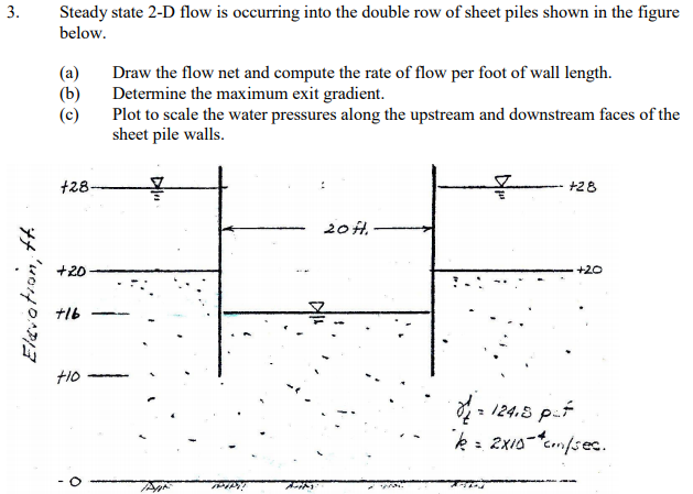
Solved 3 Steady State 2 D Flow Is Occurring Into The Dou Chegg Com
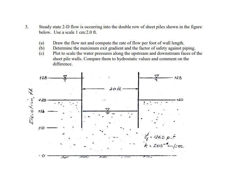
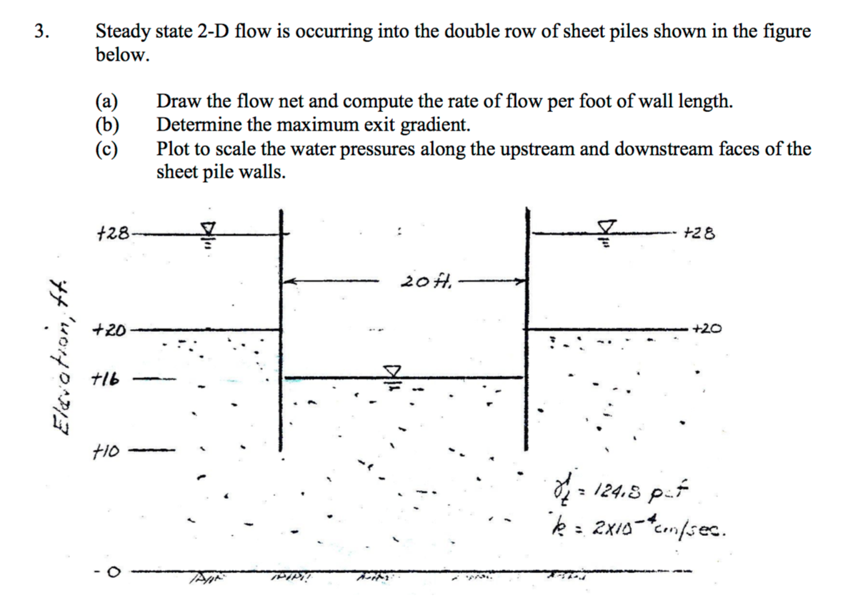
Steady State 2 D Flow Is Occurring Into The Double Chegg Com
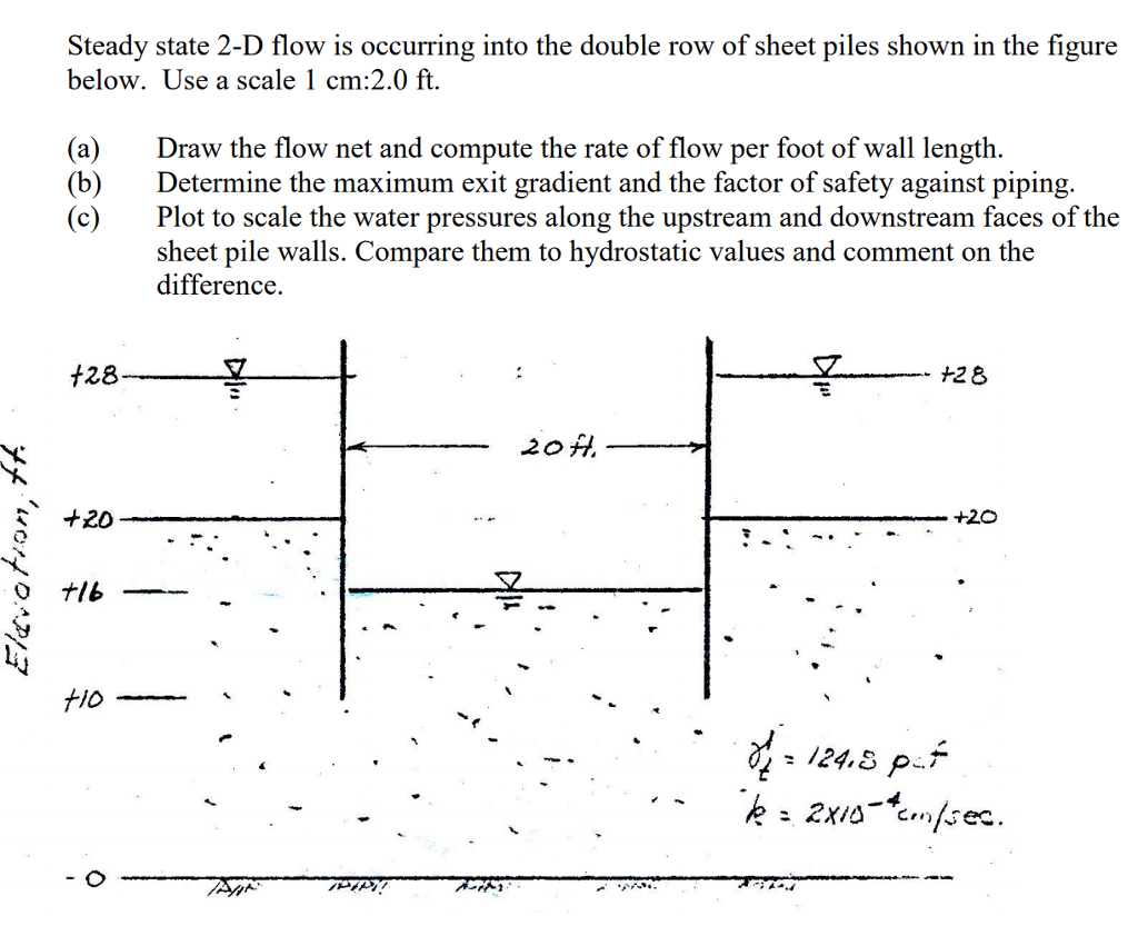
Solved 3 Steady State 2 D Flow Is Occurring Into The Dou Chegg Com
Solved Geotechnical Engineering Problem Answer For B Is Chegg Com
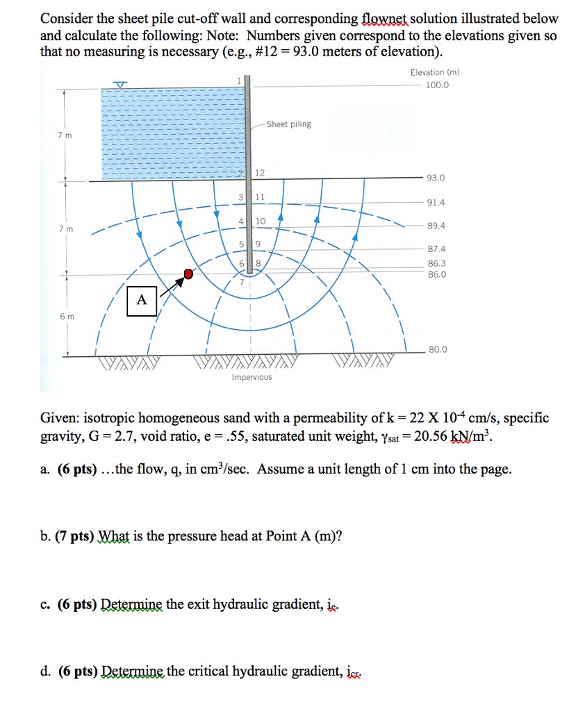
Solved Consider The Sheet Pile Cut Off Wall And Correspon Chegg Com

10 20 such that the factor of safety against heave piping is improved as shown in f w w f f s 10 47.
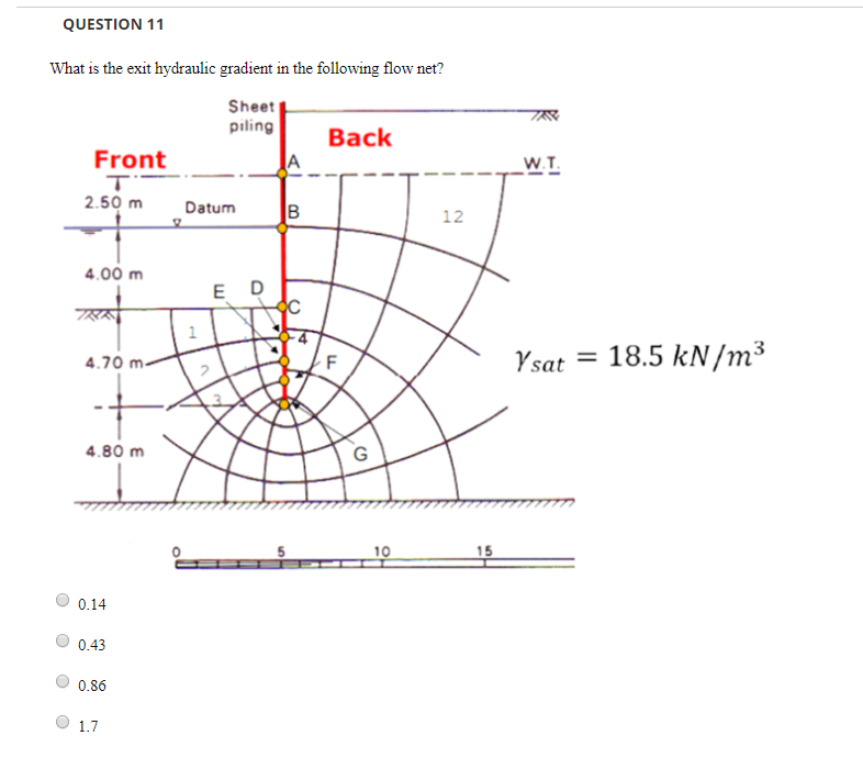
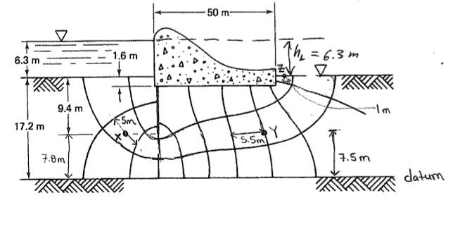
Exit gradient sheet pile wall.
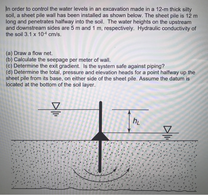
Solved In Order To Control The Water Levels In An Excavat Chegg Com
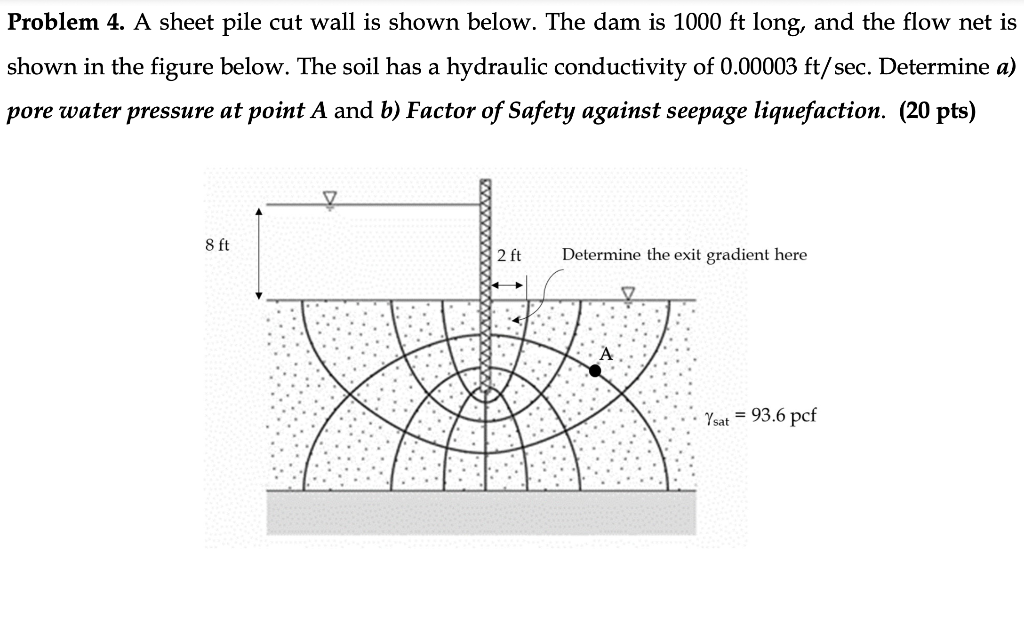
Solved Problem 4 A Sheet Pile Cut Wall Is Shown Below T Chegg Com
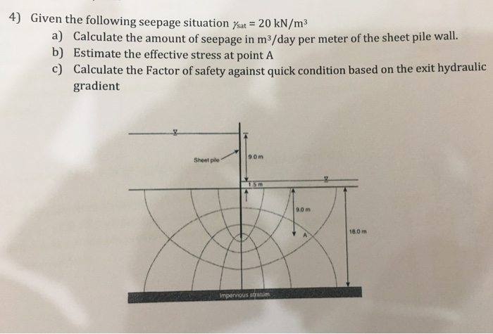
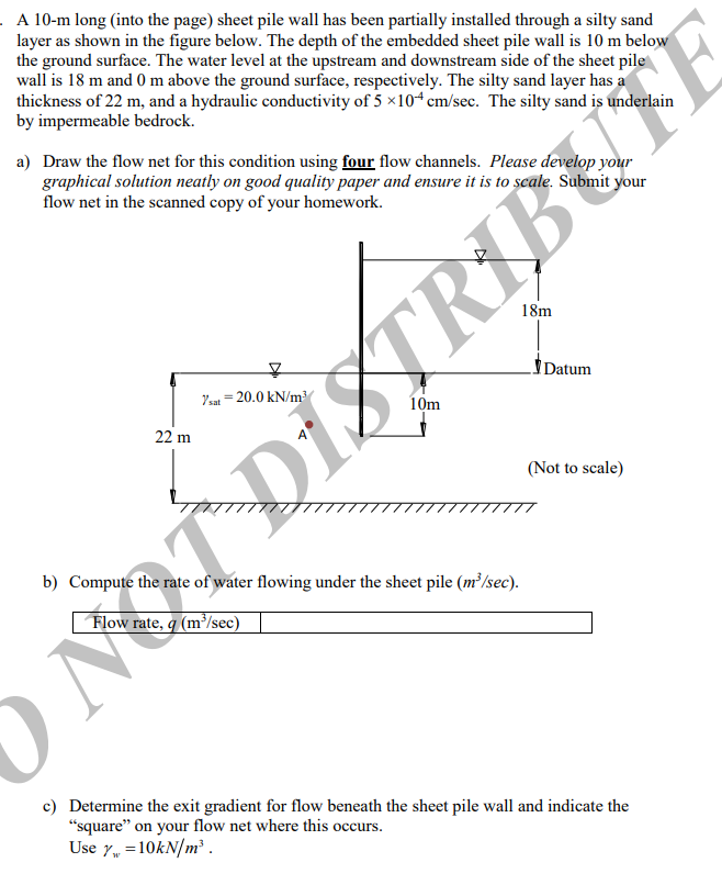
Solved 4 Given The Following Seepage Situation Ysat 20 Chegg Com
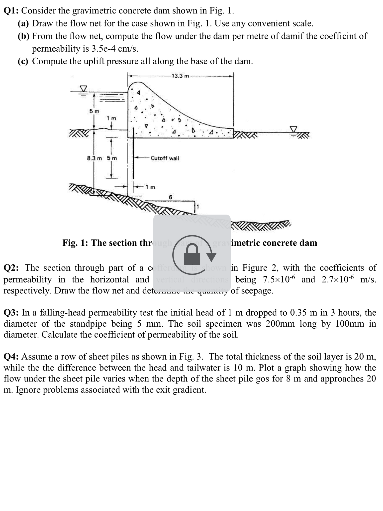
Solved Soil Mechanics Geotechnichal Engineering Consider Chegg Com
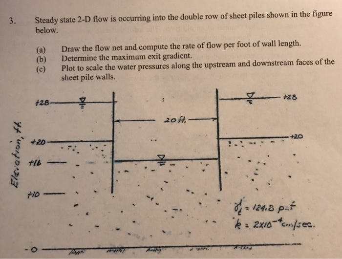
3 Steady State 2 D Flow Is Occurring Into The Dou Chegg Com
Solved For All Problems Requiring Flow Net Sketches Draw Chegg Com
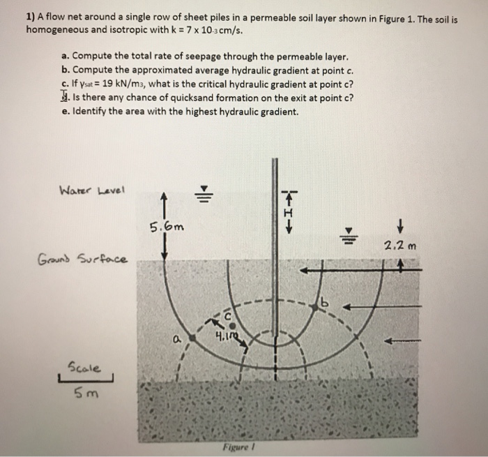
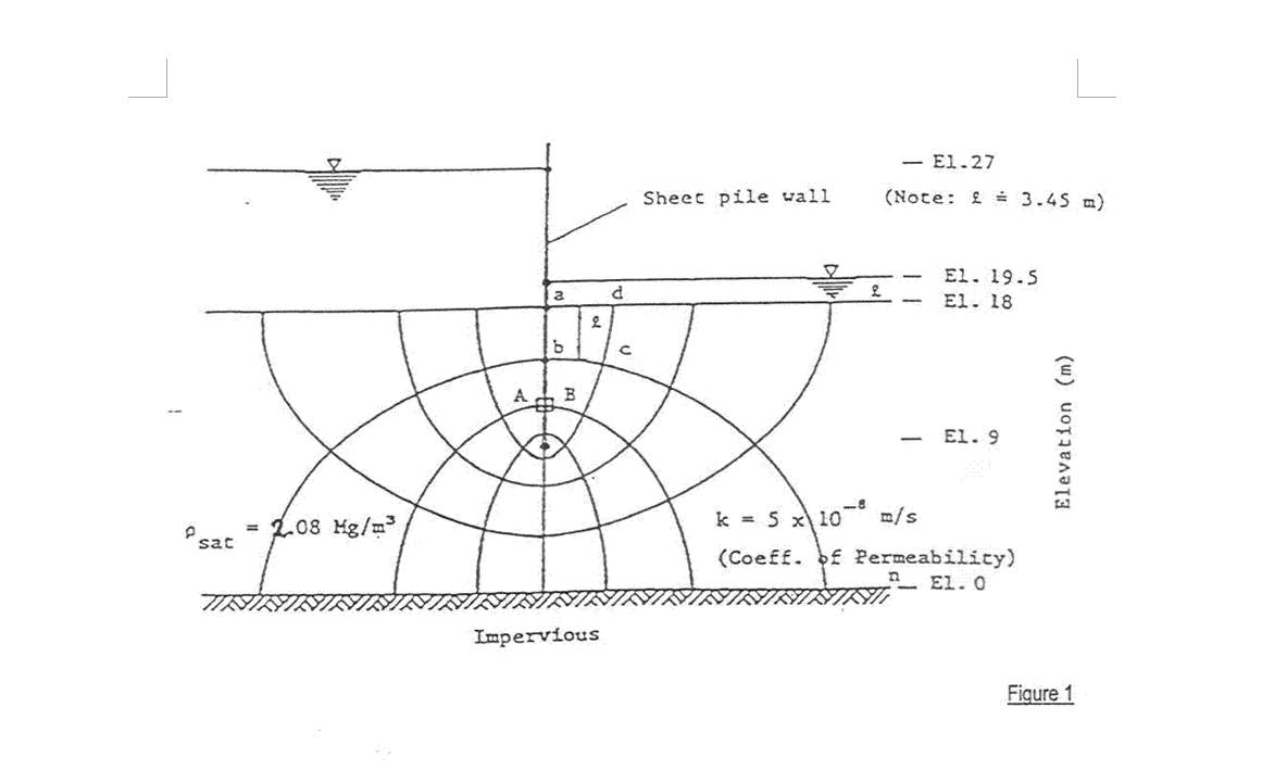
Solved A Flow Net Around A Single Row Of Sheet Piles In A Chegg Com
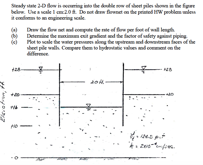
Steady State 2 D Flow Is Occurring Into The Double Chegg Com
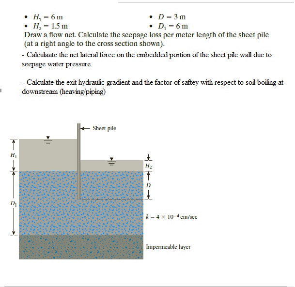
Solved D 3 M Hz 1 5 M Draw A Flow Net Calculate The S Chegg Com
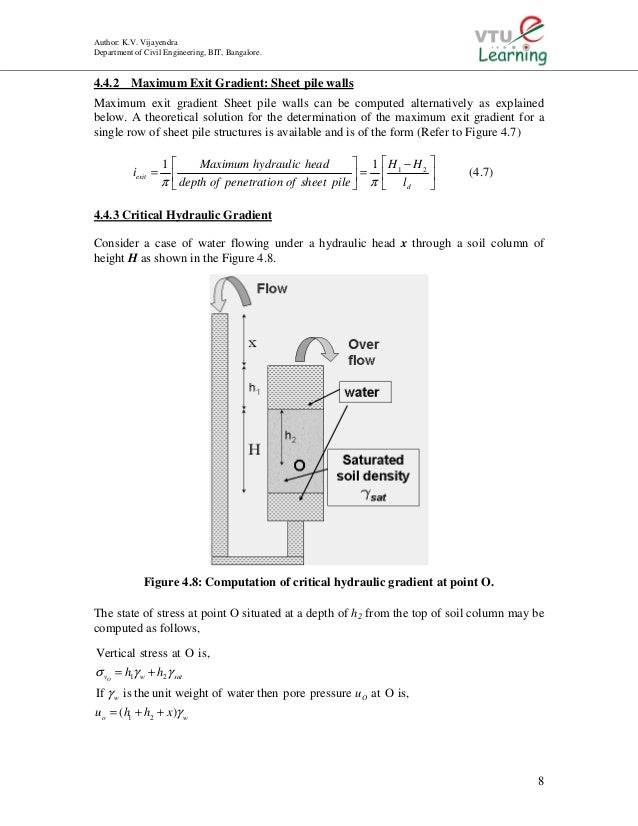
Unit4 Kvv
Solved 1 The Flow Net For A Sheet Pile Cutoff Wall Is Sh Chegg Com
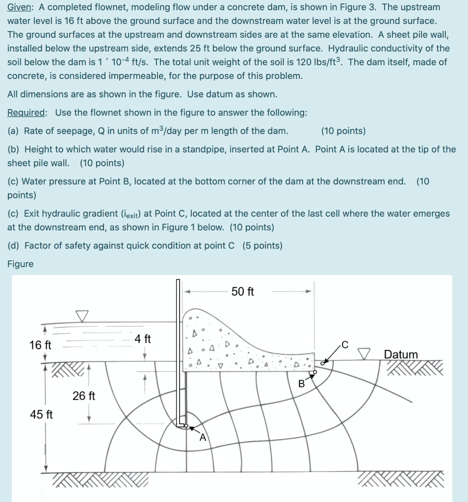
Solved Given A Completed Flownet Modeling Flow Under A Chegg Com
Http Www Bookspar Com Wp Content Uploads Vtu Notes Civil 6th Sem Geo2 64 Unit 4 Flow Nets Pdf

Pdf Design Charts For Sheet Piles Downstream Blanket Systems

Sketch For Calculation Of Exit Gradient A Computer Program Was Download Scientific Diagram
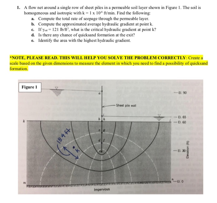
Solved A Flow Net Around A Single Row Of Sheet Piles In A Chegg Com
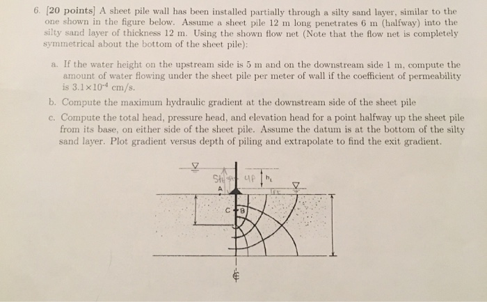
Solved 6 20 Points A Sheet Pile Wall Has Been Installe Chegg Com
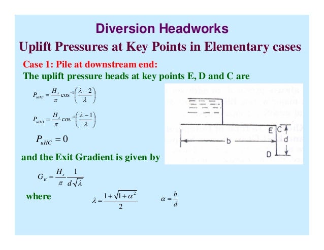
Design Of Hydraulic Structures
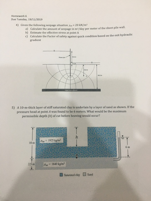
Solved Homework 6 Due Tuesday 19 11 2019 4 Given The Fo Chegg Com
Solved Given The Flow Net Below K 3 5x10 4 Cm Sec A Chegg Com
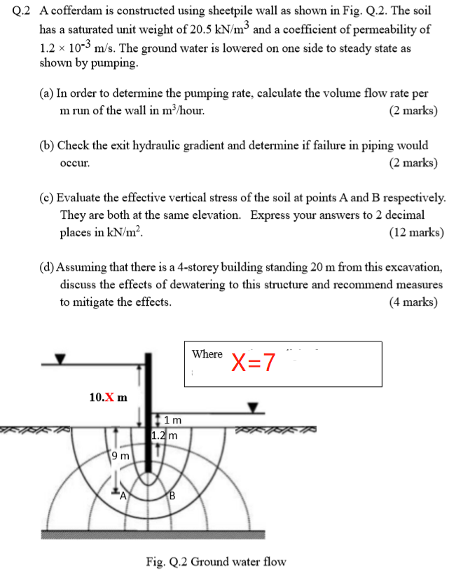
Solved Q 2 A Cofferdam Is Constructed Using Sheetpile Wal Chegg Com

Chapter 9 Solutions Principles Of Geotechnical Engineering 8th Edition Chegg Com
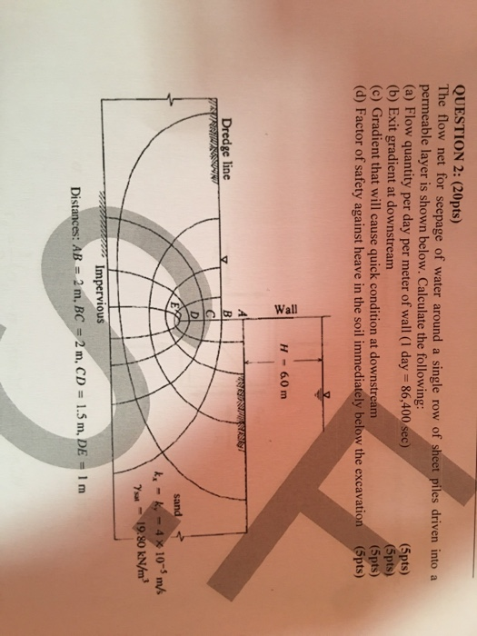
Solved Wall Question 2 20pts The Flow Net For Seepage Chegg Com
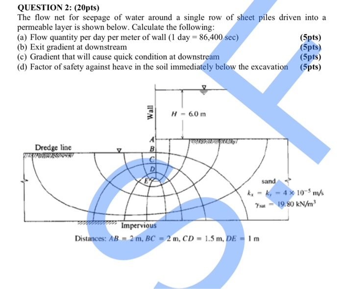
Solved Question 2 20pts The Flow Net For Seepage Of Wa Chegg Com
Source : pinterest.com
